THE SEEK AND SPEED TRANSDUCERS
The brushless servomotors by R.C.V. do represent a very important step in the production and control system of the rotary motion, but they will be able to yield their top performances only if combined to high quality electronic drives and if controlled by suitable feedback elements. R.C.V. has been installing varied transducers on its equipment, meeting with the specific requirements of each application.
Hall effect rotor position transducer
The Hall effect logical sensor consists in a miniaturised proximity semi-conductor switch, driven by a magnet, which can be operated until 120°C. The proposed size is a miniature transistor type with three axial rheophores activated by the South pole of a permanent magnet leaned onto a pre-settled surface (sensor volume 10mm³; switching distance 2mm; low outlet with magnetic induction 30 mT). The South Pole is identified as the one on each rotoric magnet of either the motor or the speed transducer marked by the same number of poles of the motors, according to the stator where the three Hall sensors are connected to. The phase shift between every sensor is equivalent to electric 120°, namely to a mechanical angle m=120°/cp (polar torque of the motor) or relating multiples, according to mechanical overall dimensions and/or the pre-settled length of the connections leads. The level of resolution which can be obtained is low, as a consequence this solution must be chosen only when the requested precision in positioning is quite relative.
Resolver
The resolver is a rotating transducer incorporating two stator windings, in-between out of phase by electric 90°, and a rotor one. By exciting the rotor winding with an alternate voltage, in a stator winding an amplitude tension will be induced which is proportional to the sine and in the other proportional to the cosine of the rotating angle of the rotor compared to the stator. The electronic processing of sine and cosine allows to identify the rotor angle at every step and, consequently, to obtain the motor angular velocity. Any error in calculating these two values, caused by the disconnection of one or more leads of the resolver, will inevitably originate a switching error in the motor phases: the power converter incorporates therefore a protection circuit stopping up operation immediately should a disconnection occur. From the construction point of view, the resolver is available both hollow and with overhanging shaft; in both cases, the adduction brushes of the rotoric current are replaced by an additional couple of windings with 1:1 ratio (the inductor is on the stator and the armature on the rotor) so called “transformer”. The most widespread used version on brushless motors is with hollow shaft (pancake), available with the transformer on the fixing side of your own stator to the motor one, too in order to avoid any interferences due to the magnetic field of the motor (they may involve both a noisy operation of the drive and a positioning error in case the converter is regulated by a motion controller). The signals of the resolver are in any case on the feeling frequency of the windings, namely around 10kHz. It will be necessary to carry out a demodulation to extract the useful signal. Special converters are universally adopted (RDC – Resolver-to-Digital Converter) which carry out the demodulation and transform the position in a digital signal at 12, 14 or 16 bit already suited to be interfaced with the digital inlets of a microprocessor. The encoder signals can be electronically obtained from the revolver (simulated encoder) to operate a positioning. This feedback element is very sturdy, it stand very well also important mechanical stress and temperatures up to 120°C.
ENCODER
The encoders are digital, angular seek transducers, they are devices with quantized angular position, namely the rotation angle of the mobile shaft is splitted in an appreciable number of parts each one corresponding to a digital signal. Mainly we can identify two types of angular transducers with digital outlet: the incremental encoder and the absolute encoder.
Rotating incremental encoder
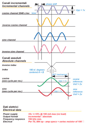
The rotating incremental encoder is a seek transducer generating two or three trains of impulse (mono- or bidirectional version), sinusoidal, featured by a certain number of impulse per each round angle of the shaft (resolution of the encoder). In addition to this, it is possible to originate a supplemental impulse for each revolution, so called zero or reference point. Particularly, when combined as primary transducer to converters for synchronous servomotors, the encoders provide for additional signals, so called the switching signals, allowing to detect the rotoric position of the motor when the feeding is activated; after this operation, the working out process will involve the incremental signals, treating them with interpolation techniques with the aim to achieve a very high resolution (steps per revolution). In a sinusoidal encoder, the switching signals are composed by two sine-cosine signals with one period per revolution. Usually a disc made up of transparent material fitted with expressly process engraved circular tracks is fixed to the hollow shaft of the encoder. The surface of the diode is lighted by photodiodes, thus providing for the moving opaque areas to intercept at intervals the light beam of the source. Opposite the photodiodes, the detecting photodiodes are located; they convert the modulated light signal into an electric signal with sinusoidal wave shape. To avoid any damage of the internal optical disc, above all if in glass, (impulses/revolution > 1000) we recommend to prevent hitting the encoder in addition to machining, pressures or bending of the pertinent shaft. The encoders with incremental and sinusoidal switching signals are featured by:
- Operating frequency 500 kHz
- Incremental signals 523 – 1024 – 2048 periods / revolution
- IP20 or IP40 protection level
- Operating temperature ranging from -10°C up to +120°C
- Highest rotating speed 12.000 rev / minute
- LINE DRIVER outlet electronic stage
- Hollow shaft
- Flexible fixing by means of leaf spring to compensate any thermal extension of the driving shaft and any eventual slight misalignments.
When determining the resolution of the encoder, we must consider that the number of periods per revolution, available downstream of the electronic multiplication (interpolation), must be sufficient to allow a seeking precision exceeding by two to four times the request of the specific application and even attain ten in case of machine tools for the metal working.
Absolute rotating encoder
The absolute encoder consists of one or more discs (mono- or multi-revolution) with a variety of circular tracks (one for each resolution bit) coded according to the binary or Gray system. In comparison to the incremental version, it offers the advantage to request a reference point (zero point) to obtain the absolute position, available as parallel or serial size, necessary for the direct position control of the final moving member of the unit. Since, in case of indirect position control, the absolute encoder is integrated in the brushless motor, the pertinent disc is fitted with additional tracks generating 1 Vpp sinusoidal incremental signals necessary to switch the servomotor; the number of transducers and the cost of the application is thus drastically reduced. In accordance with the most updated digital technologies, the transmission size of the absolute position is of serial type. On the other hand, the transmission size of the incremental switching signals is of parallel type due to the following two reasons:
- Thanks to interpolation we can obtain a by far better resolution than the one supplied by the absolute tracks of the encoder disc
- Such a so high resolution is not compatible, in relation to the necessary control dynamics, with the time requirements contemplated by the serial transmission.
The three most widespread types of absolute encoder within the servo-positioning field are:
- Sin/Cos incremental/absolute encoder with RS 485 bidirectional Hiperface (Stegmann) asyncronous serial interface
- Absolute rotating encoder with RS 485 unidiretional SSI (Stegmann) syncronous serial interface
- Absolute rotating encoder with RS 485 bidirectional EnDat (Heidenhain) syncronous serial interface.
ULTRACT
CORRELATED PAGES
ULTRACT
TECHNICAL DATA SHEET
![]() Overall dimensions and safe operating areas – UL04
Overall dimensions and safe operating areas – UL04
COME RAGGIUNGERCI
a RobassomeroLa R.C.V. ha sede nella zona industriale di Robassomero, comune della seconda cintura di Torino.
Arrivando dalle autostrade di Aosta (A5) e di Milano (A4) occorre imboccare la tangenziale di Torino in direzione sud, arrivando dal Frejus (A32), da Piacenza (A21) o da Savona (A6) occorre dirigersi verso nord.
Uscire a “Venaria – stadio” e svoltare al semaforo a sinistra, direzione Lanzo.
Attraversare l’abitato di Venaria e percorrere la S.P. N° 1 per circa 8 km, si costeggia il muro perimetrale del Parco Regionale della Mandria, fino al semaforo della zona industriale di Robassomero.
Svoltare a destra, quindi alla prima via nuovamente a destra, questa è v. Cavour.